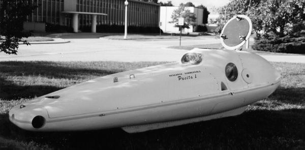
Research Submersible "Pacita 1"
General Submersible Description:
The submersible is a one man, one atmosphere fully self contained system designed to allow exploration to 400 FSW in a comfortable "shirt sleeve" environment for extended periods of time. It consists of a pressure resisting hull which is the pilots compartment. This hull is mounted into an external structure which is free flooding and fully faired. This free flooding exostructure houses the following systems which are constructed as to be compatible with being immersed:
ballast system
high pressure air system
propulsion and steering motors
main and auxiliary battery systems
The submersible utilizes a closed circuit life support system where C02 is absorbed and 02 is added to maintain normal atmospheric constituency. In addition there is a system for surface ventilation. Propulsion and steering is electronically controlled using two joysticks. Buoyancy is controlled using three independent ballast tanks which are adjusted by allowing water in or forcing water out with air.
Subsystem Descriptions:
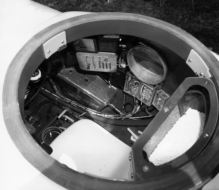
* Pressure Hull
The pressure hull is roughly the shape of an egg with a truncated cone protrusion. It is constructed of hand laid up epoxy fiberglass to a thickness of from 1.5 inches to 3 inches depending on the location on the hull. It is designed to accommodate a person in a normal upright sitting position along with all necessary equipment and controls. It is equipped with three "O" ring sealed removable feed through plates. These are designed to accommodate hull penetrations for piping and electrical. There are four viewports. Two 8 inch on either side and one 5 x 15 inch in the front. There is one 4 Inch viewport at the bottom looking straight down.
* Hatch cover
The hatch cover is constructed of welded mild steel. It is equipped with three dogging mechanisms which are operable from inside or out. The main seal between the hatch cover and the pressure hull is one 22 inch diameter 3/16 inch cross section "O" ring. The dogging shafts are double "O" ring sealed. The weight of the hatch cover is counter balanced with heavy duty springs to allow easy opening.
* Viewports
All viewports are 1.5 inch thick machined and annealed acrylic plastic. Three viewports are machined at 45 degree angles and bonded into mating holes on the pressure hull. This bonding accomplishes viewport retention and sealing. The lower viewport is sealed with an "O" ring and is bolted down. The placement of these viewports being dictated by human factors, necessitated putting them in a position on the pressure hull which caused them to be tilted Inward at the top due to the shape of the pressure hull. This tilting combined with the refractive effect of the acrylic/water interface would normally cause an unacceptably high viewing angle. An innovative use of a fluid lens concept nullified these effects. Fluid lenses are fitted to the front and side viewports and provide a very low viewing angle for observation of objects on the bottom close to the vehicle.
* Life support system
C02 generated by your body is removed by a variable speed fan forcing the atmosphere of the pressure hull through a container of soda-lime. Oxygen Is bled into the pressure hull at the same rate that it is used by the body. In this way the constituency of the atmosphere is kept essentially constant. Instruments are available in the pressure hull to measure concentrations of C02 and 02.
There is an oxygen flow meter to measure bleed rate and an aircraft altimeter to verify a one atmosphere condition. Duration of the system is limited by the amount of soda-lime that can be carried. In the current design this is about the equivalent of 12 hours.
The powered surface ventilation system can change the air every three minutes inside the pressure hull regardless of surface wave action. It is designed to be able to automatically digest and expel water that may be ingested due to possible periodic emersion.
* Buoyancy control
There are three separate ballast tanks. There are two in back on either side and one in the front. This allows fore/aft trim adjustment and side to side trim adjustment. Buoyancy can be adjusted by 300 pounds. These are hard tanks that are fully sealable with valves. There Is no change in buoyancy with depth. They are filled by opening valves to allow water to run in and they are emptied by introducing pressurized air. There is an electrical status panel in the cockpit to indicate how full the tanks are and gauges to indicate the various tank pressures ' Any possible failure mode of the buoyancy system can be nullified by the dropping of a lead weight in the bottom of the submersible which will result in an immediate ascent.
* Air supply systems
240 cubic feet in three separate bottles. This air is used for compensating various components and operation the ballast system. There are two separate and isolated air systems for redundancy and these are cross connectable. An external high pressure fill fitting Is provided to fill bottles without removal. Gages measuring high and low pressure air are in cockpit. A 14 cubic foot SCUBA bottle is in cockpit and is the third option for dropping the air actuated emergency lead weight.
* Main battery system
Consists of eight modified lead acid batteries of six volts each. These are series parallel connected for a total of 880 amp hours at 12 volts. Batteries are completely sealed and immersed in sea water. All cells are manifolded together and connected to a regulator which keeps the inside of the battery at the same pressure as the ambient sea water. All batteries can be isolated from one another for maintenance. Battery system is connected to a current measuring shunt and a 200 amp battery select switch for selecting main or auxiliary system. All motors and systems are individually fused. Operator has access to fuse panel.
* Auxiliary battery system
One 120 amp hour 12 volt lead acid battery. Pressure compensated with isolated system. All wiring Isolated from main system. For operation of life support and communications in case of main system failure.
* Motor control system
All motors are proportionally actuated by two joysticks. The joystick operated by the right hand operates the front four motors. The front thrust vector can be rotated through 360 degrees and proportionally actuated in intensity. The left joystick actuates the rear main fore/aft thrusters. All motors are automatically reversible in response to joystick position. The motors are driven by power FET transistors in a pulse width modulation mode where motor power is a function of the duty cycle of the voltage pulses which are in turn proportional to joystick position.
* Fore/aft rear propulsion motors
Two 12 volt D.C. permanent magnet motors of 30 pounds max thrust each. Motors are mounted recessed into fairing and are pressure compensated with air to equal the ambient pressure.
* Front steering motors
Four reversible 12 volt D.C. permanent magnet motors of 23 pounds thrust each. One points up, one down and one to either side. All are electronically controlled in response to joystick position in order to push the bow of the submersible in any direction.
* Radio communication
A three watt VHF F.M. radiotelephone is carried in the cockpit. It is connected to an antenna mounted in the snorkel mast. This has proved to be very effective while on the surface.
* Acoustic communications
While not yet installed, a through the water acoustic communications unit is planned. Appropriate wiring is currently in place for its installation.
* Ranging sonar
A commercial depth sounder with a LCD graph type display is installed with a switch to connect to four different transducers looking up, down, forward and to the side.
* Location pinger
For emergency location use. Operates continuously while in water.
Duration 48 hours minimum. Transmits a 34 KHZ pulse once per second.
Directional, mounted on submersible in up looking position.
*Acoustic Navigation System
Continuously measures range in feet from deployable transmitter to 1000 feet. Transmitter is to be deployed from support ship, buoy or other point of reference. Receiver and display unit is carried in submersible. Transmitter and receiver are synchronized at launch and remain in sync due to ultra precise crystal oscillators. Receiver is able to measure time of flight and therefor Is able to display distance
* Exterior lighting
3200 degree Kelvin photo lamps mounted flush to the fairing. 500 watts on each side to illuminate primary viewing area. One in nose of submersible. One illuminating the area under the lower viewport.
* Manipulator system
None installed. Plans include installation of articulated manipulator on hydraulically rotatable disk on side of submersible. When not in use manipulator will be rotated to a hydrodynamically favorable and non-snaggable position.
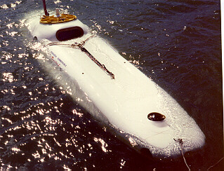
* Deployability
Submersible has a three point lifting sling that can be removed or left permanently installed. The three lift points terminate at a single ring ready to receive the hook of a lifting device. The submersible has a heavy duty skid-like underbody and can withstand rough treatment. We currently have a launch and transportation system in order to launch at boat ramps. We plan to buy or build a boat of sufficient size to deploy in deep water in order to do historic
exploration on a continuing basis.
* Testing program
The development of the submersible "Pacita I" required unique innovative solutions to many problems, many without president. As solutions presented themselves we had to do testing in order to gain the confidence to proceed. To this end, we build and operated four different testing chambers in order to simulate pressure and sometimes salt and pressure conditions. Dozens of qualification tests were performed on such things as wire insulation, motors, batteries and feedthroughs of various types. Our large chamber is four feet high and 10 feet long. We tested the entire completed pressure hull in this chamber.
Jeff Knutson
Patsy Tiemsin
benthicrov@msn.com